The long-awaited HUMAN 81 DK is now available.
Best viewed in "landscape" mode.
C3 Kit: Photographs of one I built
Back to the KC3 page In the middle of 2005 I upgraded my main living room amplifiers to a handful of Adcom GFA 555's, using three in bridged mode into all three front channels and one in stereo in the rear. This meant that I had the potential for sending over 600 watts to my center channel speaker, and I think that just might mean bad things for my trusty demo HUMAN C2 that I have enjoyed for many years. So I thought I would give myself a bit more leeway by building the first HUMAN C3 to exist. The HUMAN C3 is basically the same speaker as the HUMAN 8841, with a cabinet that is low, wide, and deep to fit the usage space, and with the drivers all shielded magnetically due to the likely proximity of a CRT-based monitor. While I was building the parts and crossovers for Alan's HUMAN 8841 project, I made an extra set for this project. The basic box is only going to be 3/4" MDF, since it is easy to buy and carry. I will be using a lot of braces and lead damping, though, so I don't think this choice will be a problem. All the parts, and some excess for braces, can be made from three 2' by 4' sheets of 3/4" MDF. All these cuts were done with the radial arm saw set up for ripping, and done in an order that allowed identical dimensions to be cut with the same set up. This might actually be easier to set up on a regular table saw with a carefully set up fence. The last cut was the "inner height" of the box, for the sides, front and back. This allowed me to keep going and cut the leftover MDF, and some spare hunks of 3/4" flooring, to the brace dimension. I decided to use the piece in the lower right of the diagram below as an extra layer for the front panel. It reaches past the woofers on both sides, and will be flanked with braces. This should create a very substantial, non-resonant mounting location to resist and damp all that energy being generated at what is basically the weakest point on the cabinet. Part of the reason for the dimensions I chose is the constraint of the shelf under the TV on my home made stand. It is a full three feet wide, and slightly over two feet deep, but only allows about ten inches of clearance to "put things on it." So my boxes will be 36 x 24 x 10, yielding about 3.8 cubic feet (before losing some volume to braces). This is a very good volume for this system, although the design is very forgiving of being reduced - see the speakers I built several years ago, which are quite similar and only in two cubic foot boxes. They have a nice, strong, tight, extended low end that has never made me wish they were bigger. Here, from my notes, are the cuts laid out on the MDF sheets, with the order of cuts to set up: 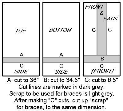 This first picture shows the basic panels laid out for a test fit, with some of my braces set up for looks as well: 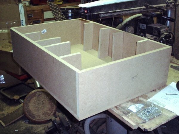 The next step is to use my router and "compass jig thing" to cut the rabbetts and through holes for the drivers: 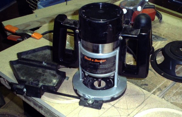 When doing the rabbetts, be sure they not only have the correct outside diameter, but that the inside diameter is smaller than the through hole will be: 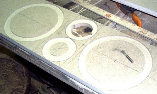 Although I am using a router and accessory to make these holes nice and round and to set the drivers into the baffle a bit, a careful hand with a jigsaw can be used to cut good enough holes. The rabbetting of the driver holes is just a vanity thing that can make the finished product look a little nicer - if you like that sort of thing. I partly did it because I am not going to bother with a grill of any kind (to match the rebuilt EPI 1000's that are the main front speakers). A nicely made grill, of course, hides however you decide to cut the driver holes. This shows the braces glued in (I put the top panel in place and weighted it to clamp them as they dried) and some lead lining: 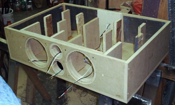 A close up of the inside at this point, with the crossover boards mounted, and the midrange chamber barely visible in the foreground: 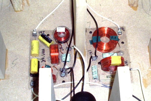 I have pulled the wires through and connected them to each other so they don't get lost, and added the damping material to the inside. This shows an alternate assembly order than I usually use - instead of finishing the box before adding any components, with this brace-filled, rather deep cabinet, it was easier to put the inner works in place before adding the last panel: 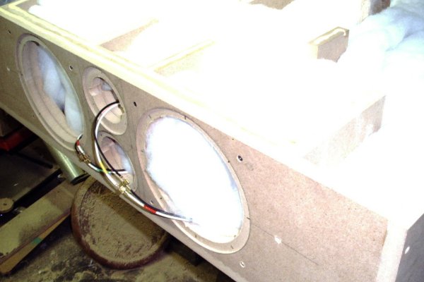 Next I glued and screwed the top panel in place, and painted the rear of the box black. I also shot the front mounting rabbetts with some paint, so any visible wood after covering them and installing the parts will not be visible. The front, sides, top and bottom will be covered with speaker fur. I see no reason to bother with this on the back. In fact, I could probably have simply painted the whole thing black and all would be well. since as is typical with center channel speakers, only the front will be really visible. But I am partly trying to "match" the EPI 1000's I rebuilt that are my left and right main speakers. I may even try to put some thin walnut trim on the front edges someday. Here is what it looks like after a late night session with some 3M Super 77 and an eXacto knife: 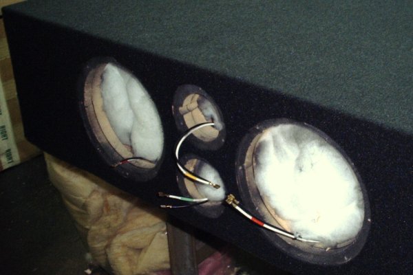 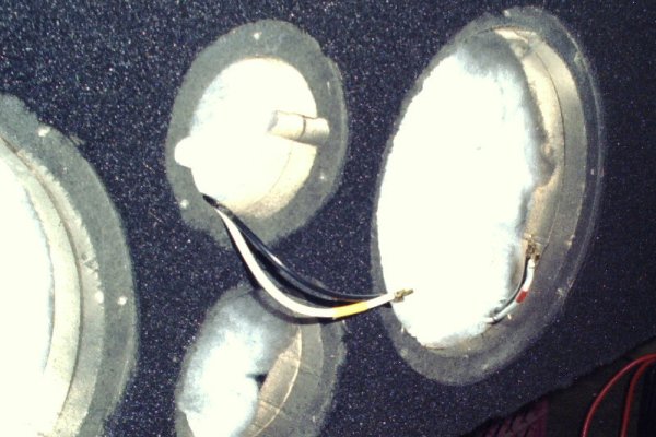 Somewhere around this time I also marked and drilled small pilot holes for all the mounting screws. This is a well-advised step, as the screws bite in much more smoothly and quickly, reducing the chance of slipping and hurting the parts while trying to get the screws started. Here are the drivers. They are magnetically shielded to prevent video interference with extra "bucking" magnets glued to the rear (you can't really see this here, but note how high the woofers are due to the extra inch or so of magnet structure thickness), and I have chosen the butyl surround option on the woofers: 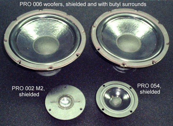 Now all that remains is to install the drivers in the front: 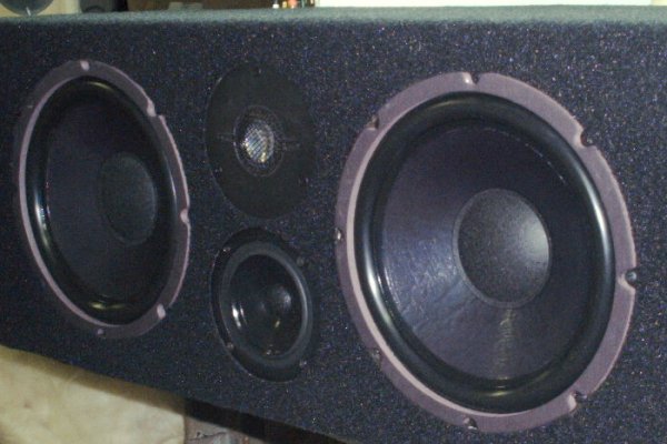 This speaker now seems to be too heavy for me to pick up safely (it was so easy when it was just the front, sides, back and bottom!). Let's see what the shipping scale says... um, ok, about ninety pounds, the same as a complete 8841. No wonder. Well, at least I can use a dolly to get it into my living room. I hope you can see how there are many planning stages to a project like this, involving materials, tools available, planned location, and possible future uses. If these are well thought out in advance of embarkation on the project it will be much simpler to build and easier to integrate into your living space and lifestyle. I should admit, at this point, that I managed to make this speaker slightly too wide (by about 1/32") to fit between the front uprights of my stand. Luckily, the shelves are 26" deep , which let me slide the speaker in from the side. Whew! measure twice, cut once, eh? "But Daddy, you've cut it twice already and it's still too short!" 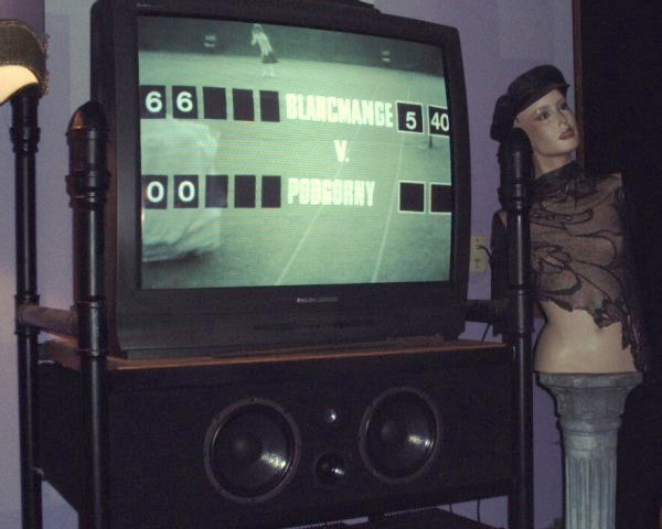 Well, there it is - tipped, leaned, levered and slid into position, and my back still works! Although, it appears that Angus Podgorny is in trouble at Wimbledon. Next! See ten years later when I turn it into a C3+. * * *
© Copyright - All Rights Reserved
Seven Kelsey Road, Lee, New Hampshire 03861 Prices can change and specifications will improve without notice |