The long-awaited HUMAN 81 DK is now available.
Best viewed in "landscape" mode.
| Sound & Hearing Recordings |
Woofers, Tweeters Passive Radiators |
Acoustic Suspension Crossover Networks |
Loudspeakers Subwoofers |
Ideally, a speaker would use one "thing" that could react to the complete electrical input representing the sound it has to produce. Unfortunately, this sound presents such a wide range of requirements that in reality more than one "thing," or driver, is required to do the job well. The lower frequencies require a lot of power, and that a lot of air be moved, which tends to lead to a larger "thing," built ruggedly, which cannot do what the highs require - lightness in order to move back and forth very rapidly, up to 20,000 times a second.
So a designer will use more than one kind of driver in a speaker. At the simplest there will be a larger, stronger piece called a "woofer" to handle the lower range and a smaller, lighter one called a "tweeter."
It is possible to design a woofer that will simply reject the higher frequencies and therefore not reproduce them badly - possible but rare - not many speakers besides those represented on this site bother to do so! The trouble is, the delicate, small tweeter will still be overwhelmed by the energy in the part of the spectrum that it is not expected to reproduce unless something is done to eliminate, or filter out, those frequencies.
This is the job of the crossover network - also known as a filter network. The incoming signal is "divided up," usually using reactive electronic components, and passed along to the individual drivers so they can do the job they were designed to do. The crossover is sometimes referred to as the "brain" of the speaker. I do not like this phrase, since in a truly intelligently designed speaker, the crossover will be simple and the drive units will represent the thinking and engineering "brains" invested in the system.
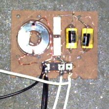
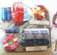
The two basic building blocks of crossovers are capacitors and coils. Fixed value resistors are also employed, but do not vary their characteristics by frequency like the first two. Put rather simply, these are all used to place some "resistance" (or more properly, "impedance") in line with some other part of the circuit.
Essentially, a capacitor is a "high pass filter." It will not pass DC current at all - DC is the equivalent of a frequency of zero - but alternating, or varying, voltages will get through. The resistance of a capacitor is inversely proportional to frequency - that is, as the frequency rises, its resistance drops.
At very low frequencies, its resistance is so high that virtually no signal is seen across the fairly low resistance driver following it. At higher frequencies, the resistance drops to the point where it is equal to that of the driver - at which point one half of the energy gets to the driver. This is typically described as the "crossover point," and it will be where the other driver is also producing, on its own or via a network, one half of the output generated over its useful range.
A capacitor on its own can serve to protect a tweeter from low frequencies - and in a well designed system, using appropriate drivers, is all that is necessary to apportion the signal as needed.
A coil works the opposite way - its resistance to DC current is almost zero (not zero because of the resistance of the wire used), and as frequency increases, its resistance increases proportionally. A coil is a "low pass filter."
A coil can be used to prevent a woofer from being fed higher frequencies, if that woofer would respond to those frequencies in an undesirable (distorted, or directional, say) fashion. Most early EPI, virtually all Genesis, and all HUMAN speakers use woofers that do not produce unwanted frequencies and thus do not require this power robbing system.
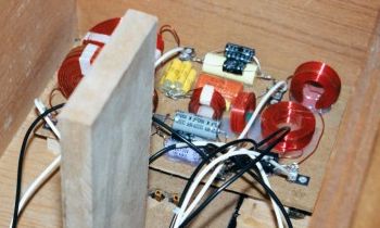
Coils and capacitors (and resistors) can also be used in more complex ways, to increase the sharpness or alter the shape of the crossover. A "single pole" filter, as described above, will reduce the output of the driver past the crossover point by one half for every doubling (for a low pass, or halving for a high pass filter) or frequency. This is known technically as a "6 deciBel (dB) per octave " slope. Using two different parts in tandem in a "double pole" network will create a "12 dB/octave" filter - the unwanted frequencies are filtered out twice as fast as you move away from the crossover point.
This concept can be taken further, leading to the development of very complex crossovers, with 24 or even 36 dB/octave filters. There can be some serious drawbacks to these very complex systems, though:
- They "store energy." The nature of how capacitors and coils pass current is complicated, but basically they act a bit like weights bouncing on springs - they do not "hand over" the signal immediately, but "smear" it a little over the time axis. This is called "ringing,"
- Another aspect of this energy storage concept is that the relationship between the voltage and current flowing through these devices becomes different that it was in a "straight wire." The current will lag or lead the voltage applied, and the problem is that the voltage represents the musical signal but the current is what actually moves the drivers cone. This is referred to as the "phase response" of a device - some say it is quite audible, and others are not so sensitive to it.
- They are much more demanding of accurate components, which although possible to obtain, can get expensive in a hurry.
- They reduce efficiency, which is how loud a speaker will play for a given power input. Some of the amplifier's power is wasted heating up the coils and resistors in a complex network instead of moving voice coils in magnetic fields.
A well-designed filter of this type can be a boon, though. It enables the designer to get more power handling out of high frequency components, by reducing even further the bass energy getting to them. It can reduce the unwanted distorted signal even a well-designed driver often produces outside its "bandwidth." It also can reduce the interference between the signals produced by the separate drivers, since their overlap at the crossover point is much narrower. Certain careful "alignments," or combinations of filters, can even eliminate the phase problem described above.
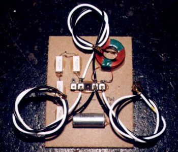
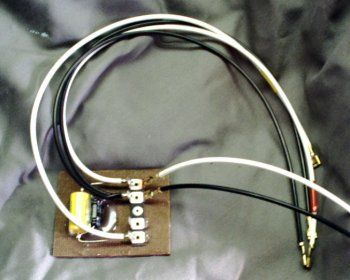
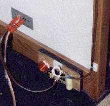
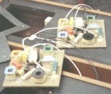
The crossover is usually mounted inside the speaker box, sometimes on a separate board, with wires connecting it to the input terminals and the idividual drivers. Sometimes the parts are attached to the inside of the terminal assembly.
There are also crossovers designed to work outside the speaker, as we see in many cheesy subwoofers - there will be an output signal, with the low frequencies rolled off, for the satellite speakers. Unless these were properly designed to go with each other, the results will be fairly poor.
I have spent all my time here describing what are know as "passive" crossovers - they simply sit in the amplified signal path and do their thing without any other electrical connections. There are also "active" crossovers, typically used before the amplifier, which roll off and split up the signal into two or more frequency-shaped parts. Then separate amplifiers are used for each frequency range. These can work very well for "true" subwoofers, which require substantial attenuation (reduction) of even fairly low mid bass signals. A passive crossover to do this would require some pretty large coils and waste a lot of energy doing it. Active crossovers are more likely to be found in multi-driver "powered speakers," or, as I said, powered subwoofers.
 |
 |
* * *
Top - Contact
New Speakers -
EPI and Epicure - Genesis Physics
© Copyright - All Rights Reserved
![]()
Seven Kelsey Road, Lee, New Hampshire 03861
Prices can change and specifications will improve without notice