The long-awaited HUMAN 81 DK is now available.
Best viewed in "landscape" mode.
This is a three way speaker using a 10" woofer, a 2" dome midrange and a 0.8" dome tweeter, all hand made, the good old fashioned way.
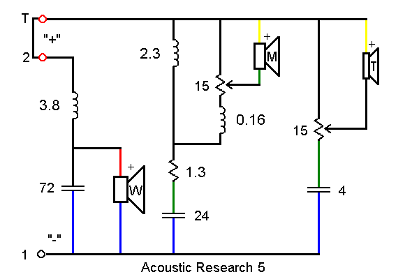
A customer brought a pair in for me to correct worn out, scratchy high and mid level controls on. We decided I would replace them with fixed resistors approximating the "recommended," or flat, position marked on the back plate. This turns out to be about 2/3 of the way "up" on a 15 ohm potentiometer.
After carefully analyzing the crossover schematic, I identified where to cut wires and solder in the resistors. I used six 5 ohm resistors in each box, three each for the tweeter and for the midrange. Basically the "-" signal goes through one of them to the driver, and also to the other two in series to positive (this crossover has the components installed on the "-" leg of the circuit).
The crossover, after close examination, is an identical circuit to the 3a crossovers I once rebuilt, but the component values are different. Unfortunately I did not measure the inductors, I was lazy and it was awkward to get in there with test leads.
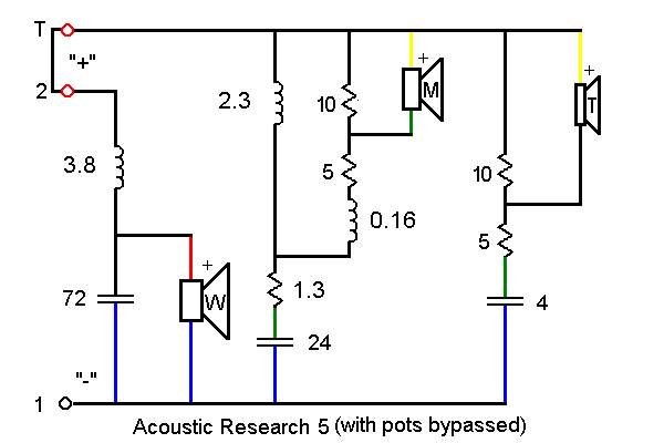
Here is the same diagram, with fixed resistors in place of the potentiometers:
Key to Crossover Symbols and Component Values (in a new window)
* * *
Top - Contact
New Speakers -
EPI and Epicure - Genesis Physics
© Copyright - All Rights Reserved
![]()
Seven Kelsey Road, Lee, New Hampshire 03861
Prices can change and specifications will improve without notice