The long-awaited HUMAN 81 DK is now available.
Best viewed in "landscape" mode.
Rebuilding EPI model 1000 Speakers
Back to the K1000 page
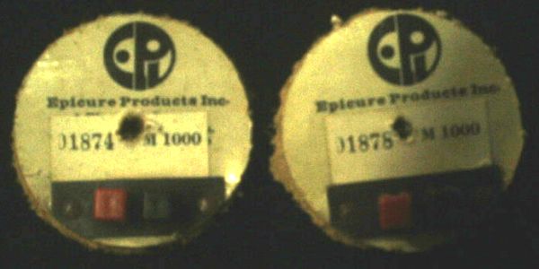
This photoessay documents the rebuilding of my vintage EPI Model 1000 speakers, serial numbers 1874 and 1878. It should be of interest to anyone rebuilding their own pair, and perhaps to hobbyists building their own using the HUMAN Speakers K1000 kit.
I bought these speakers, used, in the early nineties. I drove my decrepit old Ford F250 to Binghamton, New York in an ice storm to pick them up. For these many years, I have simply used them as they were, occasionally swapping out a woofer or tweeter that started misbehaving. I knew that one day I would want to rebuild them, but they sounded great as they were. Then one day in late 2004, or rather, one late night, I managed to blow them up fairly effectively. Now I really have an excuse to update them!
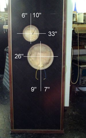
While I they are out and in pieces, I have taken some measurements, for people who want to duplicate exactly the original layout of the parts in the cabinet.
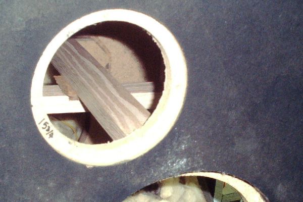
The interior dimensions are 72" x 16" x 16". The photo to the right shows the driver height from the floor, and their lateral positions relative to the outer edge of the brass trim strip. The stock shelf brace locations are approximately 19", 39", and 56" from the floor.
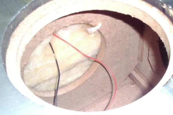
This photo shows the shelf brace directly below the woofer mounting hole:
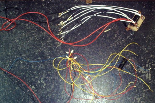
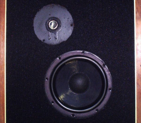
The heart of the rebuild is to install newly rebuilt woofers, aluminum dome tweeters, and new crossover/harness assemblies attached to some better terminals.
This has forced me to come up an efficient way to assemble the wiring harnesses, which is good, because I have a couple of customers who are currently working on building their own speakers using the 1000 kit. This serves as a practice run to make theirs neat and easy to work with.
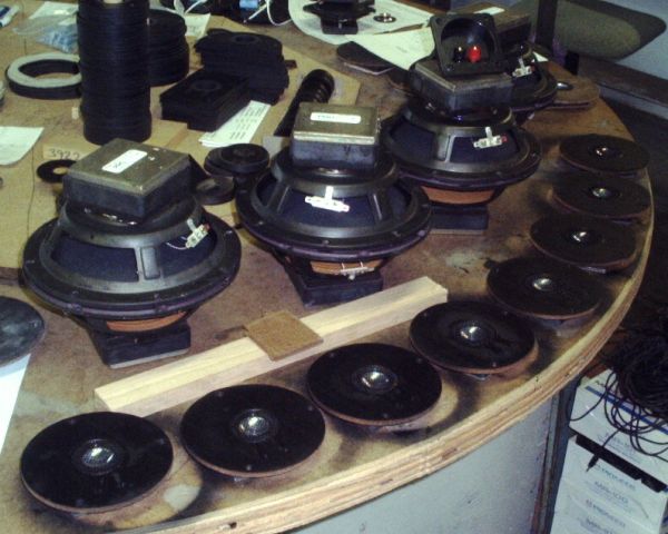
Above: the rebuilt woofers and tweeters. Below: the old and new wiring.
I am also going to add a lot of lead wherever I can, making them (even) heavier and less resonant, and add a couple of braces between the woofer and tweeter holes.
(See lead warning and handling information)
Below, showing the two crossbraces - these will also provide a convenient place to mount the crossover:
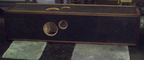
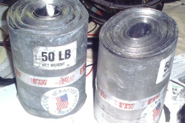
Since my grills were in poor condition (broken frames, etc.) and I didn't want to bother to make new ones from masonite, I had to come up with another "look" for the speakers. I decided to cover the entire surface of the box, top to bottom and brass strip to brass strip, with lead flashing. This is about eighty pounds per speaker (the lead weighs two and a half pounds per square foot). They weigh 180 pounds "stock" (according to the original brochure), so they'll end up at about 260 pounds. I'll cut the woofer and tweeter holes through the lead after glueing it on with construction adhesive. Then I'll cover the lead with "speaker carpet", and likewise cut the driver holes through that. I don't mind seeing the parts, since they are sort of cool anyway.
The best way to handle these huge and awkward speakers, as I discovered after wrestling one up onto my normal speaker workbench, is on the floor. By using pieces of scrap carpeting twice as wide as the cabinet, I can then work on one side at a time, then roll the cabinet so the next work face is on top, and shift it back to the same place on the carpet. The carpet will prevent marring the cabinets as I work on them. The first couple of carpeted sides will get some clean newsprint taped over them so they don't pick up any ugly dust and junk from the carpet.
So, I have built my parts (and it took that guy at HUMAN Speakers months to get them done, too! Something about a "backlog," and other customers being ahead of me!), bought the lead, carpeting, and glue. It is time to get to work!
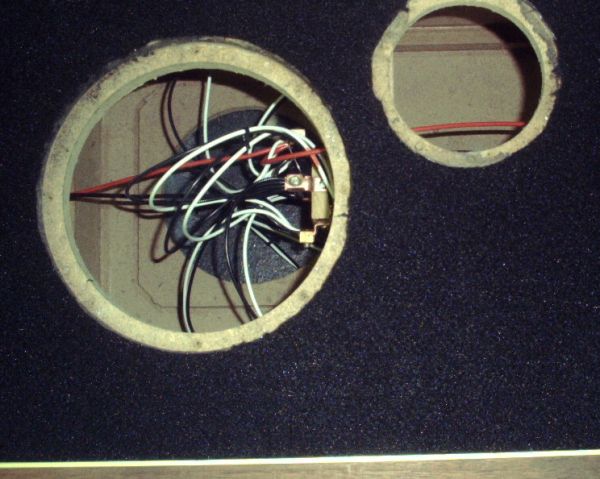
First I removed the damping material (fiberglass insulation) from the section behind the drivers. This let me cut out the rat's nest of wires that was the original harness. I'll leave the wires to the terminals in there for now, so I can use them to pull the new wires through the rest of the fiberglass easily.
Now on each face, one at a time, I hammer in the remaining nails that held the grills so they are flush, and clean up any lumpy glue residue so the lead will lie reasonably flat. I cut the lead to fit, first rolling two 8" wide pieces out and cutting them to length, then slicing 1/4" off the width of one of them. I used about half a tube of black silicone caulk/glue stuff for each face, squeezing it out all over the cabinet, then smearing the beads out with a toothed contact cement spreader. On goes the lead, which I carefully smooth out and press into the glue, using a rolling pin (which will not be used for food). I put some wood on the lead, covering most of it, and weight it down (with a couple of old car batteries I had handy).
Lead: Made in the U.S.A.! (See lead warning and handling information)
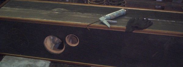
After leaving the project overnight so the glue can set, I came back and cut out the lead from the driver locations. I also remembered it would be a good idea to add the crossover and wiring sometime soon, since I will be installing the drivers on each face as I work. I used some good hot-melt adhesive to attach it under the crossbraces I installed.
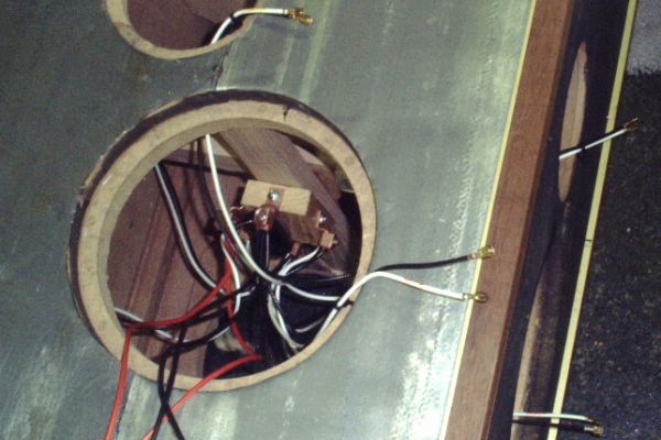
The way these speakers came from the factory the wiring harness had two sets of input wires, with terminals on the top and bottom. I'll replace both of these with some nice plastic cups and gold plated binding posts. When I build this for a DIY kit, there is allowance for just one input terminal, with the main wires about four feet long to accomodate whatever location the builder chooses for the crossover and terminal locations.
Here you can see where I have drilled out the old terminal plate (with a 2 3/4" hole saw), pulled the new wires through, soldered them to the new binding posts, and mounted the cup:
I also cleaned off all that old dust, and used some tung oil to bring the visible wood trim back to life.
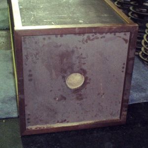
Next I sliced up a piece of speaker carpet to fit the face nicely and sprayed contact cement all over the lead, staying a few inches in from the brass and wood edging. I made sure to put a ring of glue around each driver hole. Then I laid the carpet face down on a big piece of paper and sprayed the cement in a band around its edges. Next I lined up one corner of the carpet and gradually laid it out. When it was lined up correctly, I pressed it down firmly and cut out the driver holes.
Then I drew the wires through the holes and mounted the woofer and tweeter on this side. You can also see how the walnut trim enjoyed its drink of tung oil after all these years of neglect:
The last step each day was to turn the cabinet to bring a new face to the top, glue the lead flashing down and leave it to dry.
(See lead warning and handling information)
The next day, I repeated the whole cycle - trim out the lead circles, apply the carpet and install the drivers in that face, turn and apply lead to the next panel.
Before working on the fourth side, I put the old fiberglass stuffing back in, being careful to work around the wires going to the installed drivers. Leaving it out until then made it easier to keep track of all the wires as I worked.
To halve the time lapse involved in the whole project, I could have worked on both cabinets at once, but since this was taking about two hours a day (including time spent scratching my head), and I had other speaker work to do, I was content to wait an extra few days to finally get these up and running.
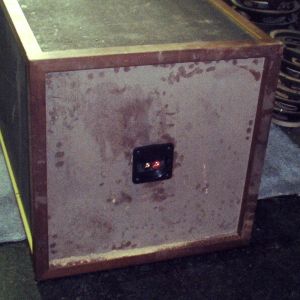
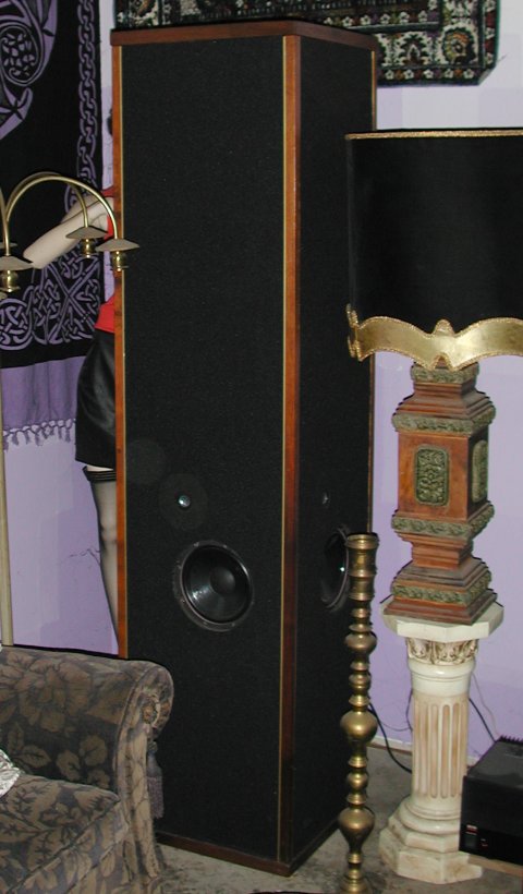
I decided after moving the finished speakers to my living room to cut some five inch circles of speaker carpet with 1.5 inch holes in the middle, to place over the tweeter faces that I could see (two per speaker). This makes the tweeter "vanish" except for the little silvery glow of the dome, and looks a lot better than the semi-flat black painted masonite face plates.
* * *
Top - Contact
New Speakers -
EPI and Epicure - Genesis Physics
© Copyright - All Rights Reserved
![]()
Seven Kelsey Road, Lee, New Hampshire 03861
Prices can change and specifications will improve without notice