 |
CIS Vacuum System |
 |
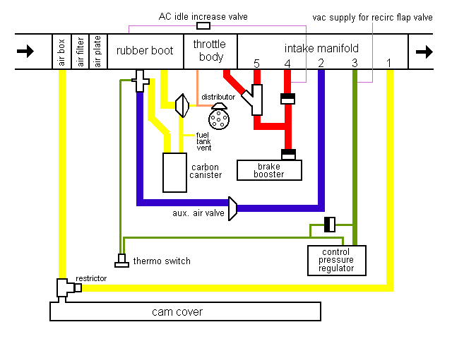
This is how the various components of the 1982 Coupe vacuum system are connected. Line thickness represents approximate hose type. The thickest are molded rubber or plastic. The intake manifold numbers indicate the connections from the throttle body forward, they are out of order for simplicity (?) in the diagram. The connections to the throttle body are both ahead of the butterflies. The AC components referenced have been deleted from my car.
Color codes:
red = brake power assist system
yellow = emissions systems - PCV and fuel tank vapor recovery
blue = cold idle increase
green = cold engine acceleration enrichment system
orange = distributor advance
purple = AC only systems

Explanation of functions:
| |
Power brakes - I dunno how it works but it seems to be set up to grab vacuum wherever and whenever there is any available. |
| |
Emissions systems - draws crankcase fumes into the intake air ahead of the sensor plate under load, at idle (closed throttle) it cheats and draws it, without letting the sensor know, into the intake manifold. There is also the fuel tank vent system, coupled with the charcoal canister. I'm still trying to figure out which direction the air flows in some of these hoses, and when... |
| |
The cold idle increase operates by allowing extra air to bypass the throttle body until the auxiliary air valve is closed. The aux air valve is powered by the same circuit as the control pressure regulator and the fuel pump, so it is always on, I presume it has a heater which causes it to close, gradually, after a preset interval. |
| |
The cold engine acceleration enrichment system is complicated. There is a pressure differential diaphragm inside the control pressure regulator which also alters the control pressure (the main control is the bimetal strip). The two vacuum lines are connected to each side of this diaphragm. Under low load conditions both sides are drawn to the same vacuum by the fat hose. Under high loads, the fat hose loses its vacuum, raising pressure on its side of the diaphragm - however the other side stays at high vacuum due to the one way valve going to it. Once the engine has warmed up, the thermo switch opens allowing the vacuum to drop on the small lines side as well. Hence, while the engine is cold, enrichment under load depends on the small lines between the thermo switch, the one way valve, and the control pressure regulator maintaining low pressure conditions. |
| |
The distributor advance is pretty simple (!), advance is determined by the pressure drop relative to atmospheric just ahead of the throttle body butterflies. When the air is moving fast, the distributor gets advanced...
In the middle of this hose there is a little vacuum actuated switch with a screwdriver adjustable center (not shown). I always thought this was some mysteriously important bit of gear. Now I know it's just a sender for the upshift light control unit.
There is a vacuum retard function as well, but only on vehicles with AC and automatic transmissions. I suppose this stops the engine from stalling when the car is coasting against the slushbox. This line is tapped in at the same source as the CPR fat hose (a Tee off connection #3) |
| |
The AC functions are as follows - whenever the AC is on, the idle is increased through the air valve by letting some extra metered air around the throttle body to the intake manifold. The other line stores vacuum through a one way valve in a canister (three tennis balls) under the right fender, and when the heater control is moved all the way to the "cold" position an electrical valve uses this vacuum to close the recirculating flap. |
 |