Starting with the 1987.5 Coupe GT (and 1987 5000) Audi went to a high compression, 2.3 liter engine using KE3 Jetronic fuel and ignition management. This is the first system that really does anything with the ignition system while the car is running - the ignition timing is fixed at 12 degrees btdc and is non-adjustable, and the electronics incorporate a knock sensor to retard the timing if detonation is present. This system is still very much like the KE system - with a minor change that is a nice improvement - the idle setting for the control pressure actuator is around 0 mA instead of 10 mA. This means that if the ECU is dead or disabled, and supplies no power to the system, the fuel settings will be close enough to right for the engine to run well enough to get you home so you can fix it. You should have the following toys get the (static) fuel mixture adjusted for maximum driveability: 3 mm T-handle hex wrench
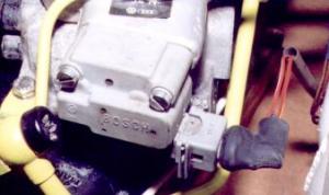
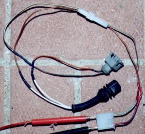
This work should be performed with the electrical systems off (do it between cooling fan cycles). Adjusting the basic settings on KE3 Jetronic requires a CO meter, really, but you can get things set without one. Two points I would like to raise here - if the car has not been "tampered" with, these setting are probably still correct and should be left alone - if the car is not running right, look elsewhere for your problems first. On the other hand, if they are set wrong, this will affect your cold starting ability since that depends on your "static" settings, and if they are way off the Control Pressure Actuator won't be able to lean or richen the mixture enough to get it to run right at all. You can run this procedure as a check on engine operation, or when replacing "tune up" parts to make sure everything is set correctly. First you hook up your meters. The current meter, set at a range that will register 0-50 mA or so, is inserted in the wires going to the control pressure actuator, using a little harness you can make or buy. When the car is at warm idle with no electrical gear running (and those pesky vent hoses clamped off!) the actuator current should "hunt" around a nominal value of 0 mA. If it does not hunt, or wander up a and down a bit around a central value, that is if it measures a consistent value, your car is not running in closed loop - something is stopping the ECU from taking over and managing the fuel system based ont he oxygen sensor output. The most likely candidates for this failure are the oxygen sensor itself, the temperature switch (in the bottom of the top radiator hose flange I hope), general wiring chaos, or a bad ECU. If this current is not in the correct range, it is adjusted by messing around in the little hole between the fuel distributor and the black rubber intake boot with the 3mm hex tool. There is a little set screw in there that adjusts the height of the air flow sensor plate arm, changing the relative mixture via the frequency valve. Clockwise for richer and lower CPA current, CCW for leaner and lower current. I like to work in increments of about 1/8 to 1/4 of a turn and work back and forth til I get it where it seems about right. You should remove the tool and rev the engine slightly before looking at the meter, to let the air plate settle in place. Do not rev the engine with the tool in place. When doing this sort of tuning work it is a good idea to check your spark plugs, cap and rotor, and be sure your air cleaner is in decent shape - otherwise you will be tuning the fuel systems to run "wrong" to compensate for worn out parts. This is also true of your various and sundry vacuum hoses - an air leak will throw everything off at idle, you will adjust for it, but it will be off by different amounts at other rpms and loads. Below are photographs of some of what is described above... (KE parts shown, KE3 similar except CPA is dark grey) The arrow points at where the Control Pressure Actuator connector is disconnected and jumpered through the adapter harness and milliammeter. The second picture is a close up of this device off the car. The third picture is the adapter harness I built for this measurement. 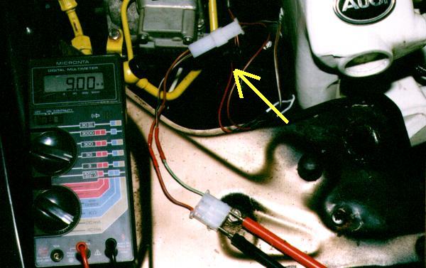
|